This post follows Designing a step-down converter - part 2.
I finally bought an AX-EL150W30A. This is a 150W electronic load, which is very useful to simulate loads and ensure that a given circuit is capable of handling large currents without resorting to resistors.
In this case, I connected the output of the power supply directly to the electronic load. The power supply is powered by a 12V power supply and a multimeter is measuring the input current. In my previous post, I was using resistors connected in series and in parallels to the power supply to reach a certain output current. I am now using the electronic load instead of thoses resistors so I have better control of the output current of the power supply. The electronic load also measures the output voltage of the power supply with 0.001V precision.
And here are the curves for both rails:
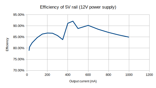
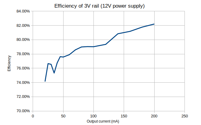
Results from the 5V rail does not differ too much from last post but it is clear that something went wrong when doing my previous measurements on the 3V rail. Both rails now show similar behaviour when output current is in range 0-200mA.
Finally, the power supply is slightly more effective at outputing 5V than 3V, which is not very surprising as those results match closely curves shown in figures 2-1 and 2-2 from MCP16311 datasheet.