Context and requirements
I am currently building a remote-controlled submarine: a 1/120 replica of the HMS Resolution. For this scale model, I do not plan to buy any off the shelf modules except the radio receiver and servos. Thus, I will design most of the electronics myself.
As several elements such as solenoid valves, pumps or motors require 12V, I preferred having a relatively high voltage for the battery instead of designing a buck-boost power supply capable of delivering several amps. The battery will consist of 4 LiFePO4 cells, reaching a nominal voltage of 14.4V.
I still need to provide 5V and 3V to power:
- the radio receiver (100mA)
- 3 servos (150mA each)
- the MCU acting as the brain of the submarine (about 20mA)
- some NOR flash chip (100mA during erase)
- some other sensors (50mA)
The maximum current for the 5V rail is set to 1A and 250mA for the 3V rail. Given these requirements, I cannot use a linear regulator as it would dissipate too much heat (up to 9.4W for the 5V rail in the worst case scenario!).
Design
To simplify the design, both power supplies will be similar, except the value of some resistors and inductors.
While looking at switching controllers on Mouser, I came across the MCP16311 and decided to use it for the following reasons:
- available in SOIC package (easier to solder than QFN or BGA)
- efficiency is over 80% even for small loads
- few external components required
- price is reasonable, less than 2$
Based on the typical application diagram found in the datasheet, this is what I came up with for the 3V rail:
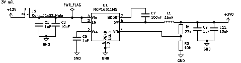
The 5V rail is nearly identical. The inductor value is increased to 22uH and R1 is changed to 52.3k Ohm.